- Home
- Service/Products
- Success Stories
- How It Works
- Downloads/Links
- About Us
- Contact
Latest Information
History of Ram Pumps
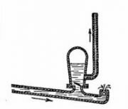
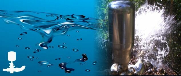
A hydraulic ram pump harnesses the power of the water hammer, the so called "ram", created by the gravitational flow of the water and the immediate stopping through a valve. The so-called "ram" which gave the ram pumps their name.
The developed power is used to lift a fraction of the total water, which is needed to power the pump, above its very origin. It is commonly used in remote areas with access to water level differentials, since it requires no outside source of power other than the gravitational energy of falling water.
The first ram pump was invented in 1796 by the Frenchman Joseph Michel Montgolfier for the purpose of raising water in his paper mill at Voiron. His friend Matthew Boulton took out a British patent on his behalf in 1797. The sons of Montgolfier obtained an English patent for an improved version in 1816.
How does a Ram Pump work ?
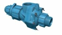
A hydraulic ram pump has only two moving parts:
a mostly weight loaded waste valve, sometimes known as the clack valve and a delivery check valve, which makes the pump operation reliable and easy to maintain.
Other non-moving parts are the drive pipe which supplying water from an elevated source and a delivery pipe, taking a portion of the water that comes through the drive pipe to an elevation higher than the original water source.
Sequences of Operation
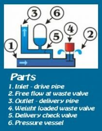
At the beginning of the cycle, the waste valve (4) is open and the delivery valve (5) is closed. The water in the drive pipe (1) starts to flow by gravitational force, picks up speed and kinetic energy until it forces the waste valve to shut close.
The momentum of the water flow in the drive pipe (1) against the presently closed waste valve (4) creates a so-called water hammer, which raises the pressure inside the drive pipe (1) and the pump body and thus opens the delivery check valve (5).
This allows a portion of the water under pressure to escape into the pressure vessel (6) and the delivery pipe (3). Since this water is being forced through the delivery pipe (3) against gravity, its flow slows down and finally reverses, closing the delivery check valve (5) closes. If all water flow has stopped, the pressure inside the drive pipe (1) equals ambient pressure, which makes the waste valve (4) reopen to allow the above cycle to start again.
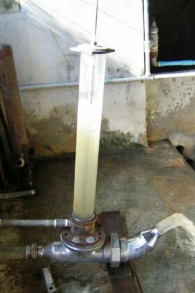
When commencing operation for the first time, or after long periods of inactivity, the pressure vessel (6) contains an air cushion, only. The latter cushions the sudden build-up of pressure, when the waste valve (4) shuts close and improves efficiency by allowing a more constant flow through the delivery pipe (3).
Although the pump could work without any pressure vessel (6), its efficiency would drop drastically and the pump structure would be subject to extraordinary stress that shortens its life considerably. As the air in the pressure vessel (6) is under pressure, it tends to disappear gradually through the delivery pipe (3). That could be solving by installing a snifting valve between pump body and pressure vessel (6).
The optimum length of the drive pipe (1) is 2 to 5 times the vertical distance between the source and the pump. With these parameters, pump cycles typically are 40 - 60 beats per minute. In order to optimize efficiency, the drive pipe (1) should be made of non-elastic, strong and rigid materials and installed as straight as possible and fixed properly on the ground.